Trying to make sense out of the "acronym-scrabble" that engulfs Service Oriented Architectures (SOA) is a major challenge. We're going to take a shot at it in this article by defining a process roadmap and following a single example all the way from architecture to code. Along the way we'll illustrate many of the key features of Enterprise Architect Business and Software Engineering Edition.
The example we'll follow will be a Service-Oriented Architecture (SOA) car rental system model, developed by the team at Sparx Systems, that's implemented with a combination of web-services and custom software. Our SOA Process Roadmap will tie everything together in what we hope will be a clear and understandable manner.
Web services and SOA have become increasingly important in today's IT universe. A recent article from IBM Global Technology Services[1] suggests that nearly half the companies in the world are either adopting, piloting, or considering SOA, and that investments in these projects may reach between $18 Billion and $160 Billion in the near future. With those sorts of numbers, it stands to reason that many readers will be interested in a roadmap and a cohesive example that brings some clarity to the problem. Hopefully this includes you.
Service-Oriented Architecture (SOA) is an approach to building complex software systems from a set of reusable services that obey service-orientation principles. Many people believe that Service Oriented Architectures can help businesses to be more "agile" -- in other words, enable faster and more cost-effective responses to changing conditions.
SOA enables construction of applications from fairly large chunks of reusable functionality that can built quickly, primarily from existing services. Thus, SOA promotes reuse at a "macro" level, and, in theory, as an organization publishes more and more business functionality as services over time, the cost of building applications that use those services decreases.
A service that obeys the principles of service-orientation is an autonomous, loosely coupled, and stateless unit of functionality that is made available by a formally defined interface. The functionality provided by a service is discoverable by applications that use the service.
Services are not allowed to call other services, but may communicate with them via messages. That is, services are loosely coupled, and each service implements a single action, such as placing an online rental car reservation.
Services are designed without knowing who will be using them. In a service-oriented architecture, applications are built from services which communicate via messages using a process known as orchestration.
A popular approach to implementing a service-oriented architecture is via web services, which make services accessible over the Internet independent of platforms and programming languages. The BPEL language is often used to orchestrate SOA applications. Building applications from services requires metadata that describes the characteristics of the services, and the data that is used. Typically, XML is typically used describe data, WSDL is used describe the services themselves, and SOAP (Simple Object Access Protocol) describes communication between services.
As it turns out, an SOA example also serves to illustrate many of the features of the Sparx Systems solution, which supports building "executable business processes" that use WSDL (Web Service Definition Language) to implement their solution. And, since projects don't live by web services alone, Enterprise Architect has numerous other useful features for handling those parts of the application that require custom (non-web service) development. In particular we'll be spending a significant amount of time exploring in this book include a new and unique capability for "behavioral code generation" for the enforcement of Business Rules, and tight integration with IDEs, including Eclipse and Visual Studio. We've leveraged the power of these capabilities into our SOA Roadmap.
As with all of our ICONIX Process Roadmaps[2], our SOA roadmap is defined as a set of activity diagrams. In this case, the roadmap provides a "cookbook" set of steps that can be followed for building systems that are based around a Service-Oriented Architecture.
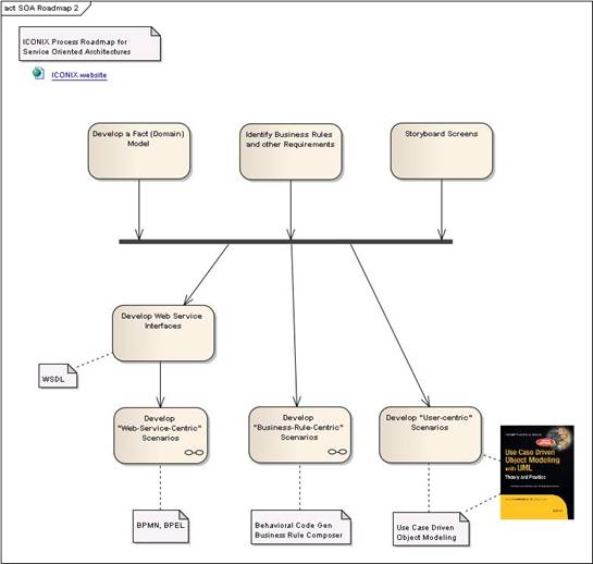
Figure 2 shows our top-level roadmap. Some of these top-level activities will expand out to a child diagram showing further detail. As you can see, the top-level roadmap includes some "common stuff" like figuring out your requirements and modeling the problem domain, and then provides multiple paths for developing different flavors of business processes, all the way to code.
As shown in our top-level roadmap, there are a few "setup" activities that will are necessary at the beginning of our SOA project. We'll begin with a simple domain model (also called a fact model), that shows the main objects in the problem domain (Figure 3).
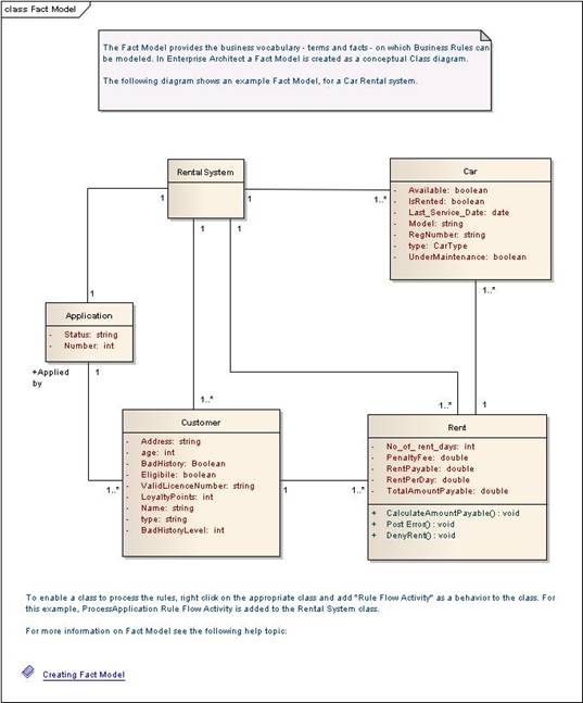
As you can see, the domain model establishes the vocabulary we use to describe our system, and shows relationships between objects in the problem domain. In most cases these relationships include UML generalization and aggregation relationships (not shown here).
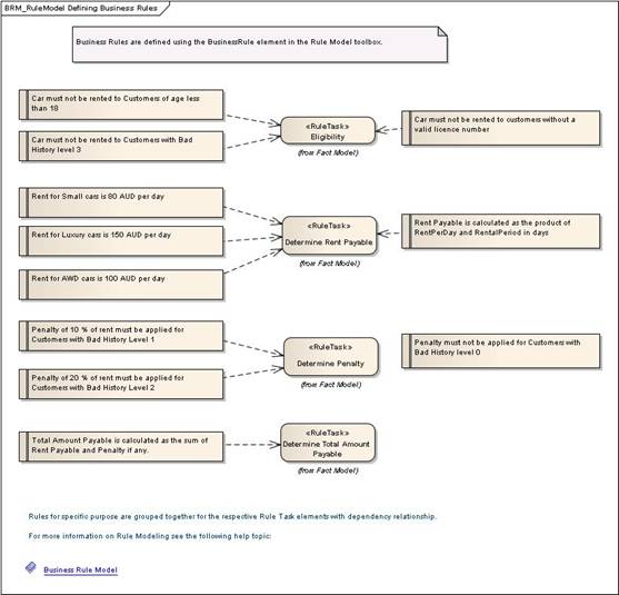
Business Rules are represented in Enterprise Architect as stereotyped Requirements. Figure 4 shows a Requirement Diagram for our Car Rental System that organizes these business rules according to different RuleTasks. We'll talk more about RuleTasks (actions that enforce Business Rules) shortly.
The top-level roadmap shown in Figure 2 reflects the philosophy that when you set out to implement a system using a service-oriented architecture, there will effectively be a mix of 3 different kinds of scenarios:
Most systems will contain a mix of these different types of scenarios.
In many cases (but not all) the "web-service scenarios" will cross Business To Business (B2B) boundaries. For example, a car rental reservation system talking to a credit card company to run a payment transaction is a B2B web-service scenario. Where a business process can be implemented via web services, we follow the branch on the left: web service interface definition using WSDL, and orchestration using BPMN and BPEL.
The "business rule scenarios" are more likely to be within the boundaries of one business, for example, the car rental system enforcing eligibility rules on driver age, credit score, etc. There is little or no user interface in these business rule scenarios, so they can be completely code generated from an activity diagram using the business rule composer. For processes that are primarily focused on enforcing business rules, we take the right branch: Behavioral Code Generation from Activity Diagrams using the Business Rule Composer.
Finally there is the user interface. These would be the screens of the car rental system that the reservations agent accesses, and which would trigger the business rule checks and B2B transactions. These parts of the system are best modeled using use cases, following a "use case driven" approach that's out of scope for this article, but well documented in my other books [3].
With all of these branches, we can compile and build using either Eclipse or Visual Studio, and use the Sparx "MDG Integration" technology to keep models and code in-synch.
Suppose you wrote an interesting application (maybe a program that automatically generated a horoscope based on your birthday and today's date), and you wanted to publish your application to the Internet so anybody in the world could purchase their horoscope from you. How would you do that? Most likely, you'd do it with a web service.
Web services support distributed, platform-independent development. Using web services, you can publish any application you choose to build over the web. A web service can be written in any language and hosted on any computer that's connected to the Internet.
The concept behind web services isn't new; previously developed similar approaches include OMG CORBA, Microsoft DCOM, and Java/RMI. You can think of a web service as something like an Internet-enabled API.
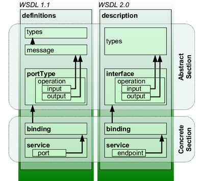
You'd describe your horoscope web service using Web Service Description Language (WSDL); an XML-based language that describes the public interface to the web service. WSDL tells you only how you can interact with the web service; it says nothing about how the web service works internally.
WSDL defines Services as collections of Network Endpoints, or Ports; a collection of Ports defines a Service. A Port associates a network address with a reusable binding, and a Message is an abstract description of the data that is being exchanged. A WSDL file has an "abstract" section that describes Ports and Messages, and a "concrete" section that describes specific instances of their usage. This file structure is shown in Figure 5.
Before we can use BPMN and BPEL to orchestrate a collaborating group of web services, we first need to be able to define the web services themselves.
WSDL Packages in Enterprise Architect are organized into Types, Messages, Ports, Bindings, and Services as shown in Figure 6.
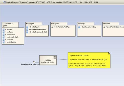
Once we've defined our Types, Bindings, Ports, Messages, and Services, it's time to generate WSDL by right-clicking on our WSDL component and choosing Generate WSDL from the context menu. Figure 7 shows the WSDL generation in progress.
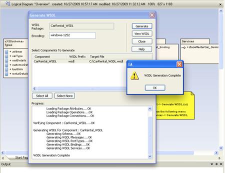
The result of WSDL generation for our Car Rental component can be seen in Figure 8.

The term "orchestration" is often used to describe implementing a business process by using a number of web services in a collaborative way. We'll use BPEL to orchestrate web services, and BPMN to model BPEL.
Note that it's possible to draw BPMN (Business Process Modeling Notation) diagrams to model business processes without generating BPEL (Business Process Execution Language). And, you can model BPEL using other graphical notations besides BPMN. But one of the more interesting strategies, which we're following in this roadmap, involves using BPMN to model BPEL processes [5].
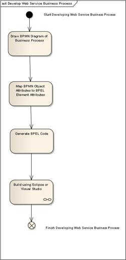
Figure 9 shows the roadmap basic steps for using BPMN to model BPEL.
BPEL is short for WS-BPEL, which is short for Web Services Business Process Execution Language. You can use BPEL to build web services, to write programs that call web services, and to describe high-level business processes that make use of web services.
BPEL business processes are often used to implement business-to-business (B2B) transactions where one business provides a web service and another business uses it. Our car rental example in this book is an example of this sort of B2B transaction.
BPEL is sometimes referred to as an orchestration language because it supports complex orchestrations (sequences of messages being exchanged) of multiple service applications. Orchestration refers to the central control of the behavior of a distributed system as opposed to choreography, which refers to a distributed system that operates without centralized control.
There is (intentionally) no standard graphical notation for BPEL, and as a result, some vendors have invented their own notations. However, many people use BPMN (Business Process Modeling Notation) as a graphical front-end to capture BPEL process descriptions.
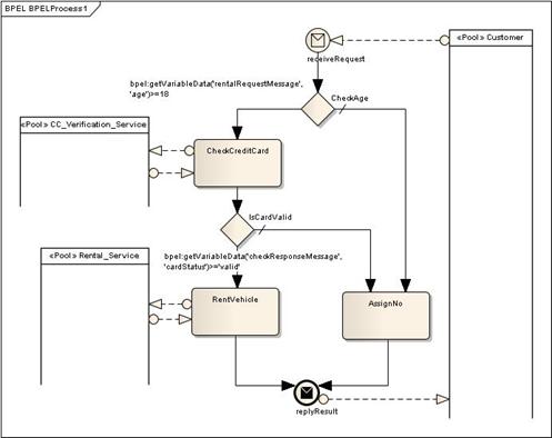
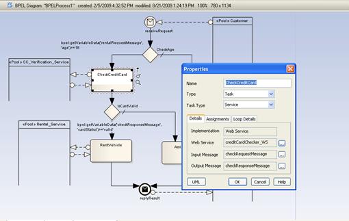
Figure 10 shows a BPMN diagram for our BPEL Car Rental Process. The process begins with a Start Event: a Request is received from the Customer. If the customer is of legal age to rent the vehicle, a (B2B) web service is used to check the Customer's credit card. If the card is valid, another web service is used to rent the vehicle, and a "Success" message is sent. If either the age or credit card checks fail, a "No" message is sent back to the customer.
Once we've defined our activities, gateways, and events on our BPMN diagram, we can specify additional BPEL details as attributes on our BPMN elements. In Figure 11, we're defining that the CheckCreditCard activity will be implemented as a web service, and will take a "request" message and generate a "result" response.
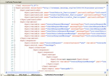
Finally, after we've specified our BPEL Process and validated the model, Enterprise Architect will generate the BPEL code to accomplish our business process.
Even in a service-oriented system, not all business processes can be implemented by orchestrating web services. Some business processes will involve user interfaces, and some will be focused on enforcing business rules. We won't discuss GUI-based software use cases in this article, but we will spend a fair amount of time discussing some new ways to implement those processes that are focused on enforcing business rules.
In this section, we'll introduce you to the unique capabilities of Enterprise Architect's Business Rule Composer. Starting from the domain model (fact model) and the requirements that we'll presented earlier, we'll take you through the process of creating Activity Diagrams for Business Processes, stereotyping Actions as RuleTasks, and finally, linking the business rules to the rule tasks in preparation for Behavioral Code Generation.
Figure 13 shows our roadmap for business-rule-centric scenarios.
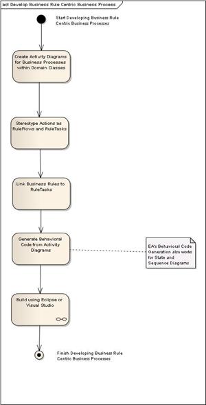
One of the common themes of all of our ICONIX Process Roadmaps is that they all get you to code. We've always believed that processes that only get you halfway to code (or less) are much better in theory than they are in practice (because in practice, programmers tend to ignore them). Enterprise Architect, since it's early days, has excelled at "code engineering" (forward and reverse engineering for a wide range of languages, powered by customizable code generation templates). But those already strong capabilities have recently taken a quantum leap in power with the introduction of behavioral code generation from activity diagrams, state diagrams and sequence diagrams. Behavioral code generation is a major advancement over generation of "class headers" (which has been the de-facto meaning of "code generation" for more than a decade).
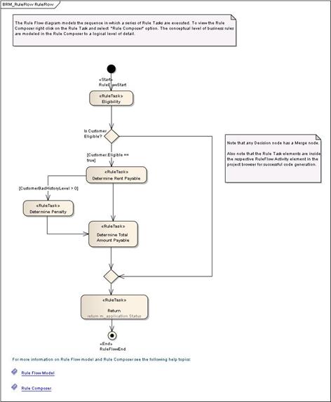
Let's take a look at how we're going to process an application for our Car Rental System. The first thing we need to do is to create a RuleFlow diagram - in this case ProcessApplication (Figure 14). We'll create this diagram "inside" of a class in the Fact Model, just as if we were creating an Operation on that class, since that is, in effect, what we're doing. The RuleFlow diagram contains RuleTask actions. Each RuleTask satisfies one or more business rules with some conditional logic.
What we'd now like to do, is to specify the conditional logic for each of these RuleTasks, while associating each piece of logic with the specific Business Rules that we're enforcing. As you might have guessed by now, that's where the Business Rule Composer comes into play. Once we've completely specified each RuleTask, we'd like Enterprise Architect to generate 100% complete code for the entire RuleFlow (Activity Diagram). Using Behavioral Code Generation, that's exactly what we'll do.
Figure 15 shows the Business Rule Composer for the "Eligibility" RuleTask.
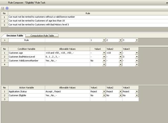
There are 2 sections on the Rule Composer screen. The top panel shows the Business Rules that we're satisfying within this Eligiblity RuleTask; the lower section (in this case a Decision Table) has 3 parts: a Condition section to model condition variables, an Action section to model action variables, and a Rule Bind section to link the rule in the rule table.
Code generation turns out to be very simple (and yields astonishing results) once all the preliminary work has been done. Simply right-click on the Fact Model Class in the Project Browser and select "Generate Code".and.Voila! No programming required!
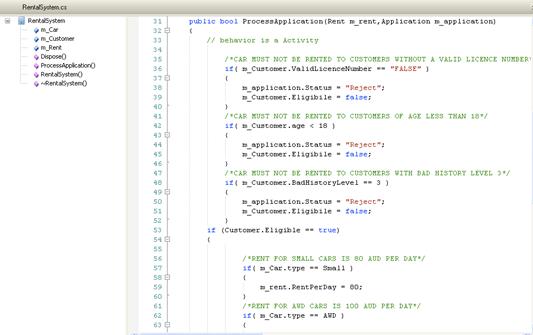
It's worth examining the code shown in Figure 16 quite carefully. Here are a few points worth noting:
It doesn't take a whole lot of imagination to see that this capability can be a real "game-changer". Many organizations have thousands of business rules to implement, and "errors in translation" between Subject Matter Experts, Business Analysts, and Programmers are the norm, not the exception. Many of those errors can be eliminated using Behavioral Code Generation and the Business Rule Composer.
Since well before UML even existed, one of the biggest issues with modeling software has been keeping the model and the source code synchronized. The typical experience used to be that UML models were most useful in getting the first release of software completed, but after the initial release, the code would evolve independently in a development environment, and the UML model would rapidly grow obsolete.
With the evolution of agile methodologies, this situation often led to projects abandoning UML modeling entirely, as agile methods specify many frequent releases of the software, and getting to the first release became a smaller and smaller percentage of solving the overall problem.
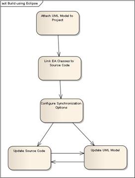
You can beat this problem entirely by using Sparx MDG Integration for Visual Studio and for Eclipse, both of which are included in the EA Business and Software Engineering Edition.
Most SOA systems will contain a mix of 3 different kinds of scenarios:
Our SOA roadmap takes all these different types of scenarios into account. We use WSDL, BPMN, and BPEL for web-service-centric scenarios, we use the Sparx Behavioral Code Generation and Business Rule Composer capabilities for business-rule-centric scenarios, and we use normal use cases where there are users and systems interacting.
We hope you find the roadmap useful in your development efforts. For more information visit ICONIX on the web at www.iconixsw.com, or contact us at SOAtraining@iconixsw.com .
[1] "Realizing Business Value from an Integrated Service-Oriented Architecture System in a Multivendor World" - IBM Global Technology Services, April 2008
[2] These now include roadmaps for Embedded Systems, Testing (aka Design-Driven Testing), Algorithm Intensive Development, and Business Modeling, in addition to ICONIX Process for Software (the original "Use Case Driven ICONIX Process"). See www.iconixsw.com for more details.
[3] See "Use Case Driven Object Modeling with UML - Theory and Practice" by Doug Rosenberg and Matt Stephens
[4] Wikipedia: Web Services Description Language
[5] We found "Using BPMN to model a BPEL Process" by Stephen A. White, IBM Corporation, to be a very useful article.
Figure 1 - A "Secret Decoder Ring" may be required for Service Oriented Acronyms