Figure 1 (right) shows the top level roadmap for ICONIX Process for Embedded Systems. As you can see, our roadmap starts off by defining requirements, proceeds through modeling of system behavior and block structure, and then through definition of constraints and parametrics, simulation, and then implementation in both hardware and software. We'll illustrate our roadmap using an example model, developed by Sam Mancarella from Sparx Systems, that describes an Audio Player.
We'll also introduce you to some unique capabilities of Enterprise Architect Systems Engineering edition, which supports advanced features such as executable code generation from UML models (including support for hardware description languages such as Verilog and VHDL), executable SysML Parametric diagrams and advanced scripting.
Each of these capabilities, taken standalone, adds a significant amount of "horsepower" to a systems engineering effort. We'll combine these capabilities into a single process roadmap that's greater than the sum of its parts.
Our Embedded System Development Process Roadmap is built around producing a SysML model that is organized into four sections. These parts of the overall system model (Requirements, Structure, Behavior, and Parametrics) are sometimes referred to as "The Four Pillars of SysML" [1]. As with UML, Packages are used to organize the model.
Requirements are generally categorized as Functional Requirements, which represent capabilities of a system, and Non-Functional Requirements, which cover such areas as Performance and Reliability. You can organize Requirements into hierarchies on requirement diagrams (see Figure 2).
EA supports allocation of requirements to other elements using a simple drag-and-drop, and automatic generation of traceability matrices.
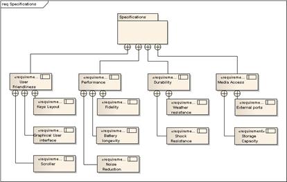
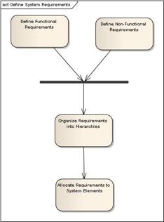
Figure 3 shows the steps for Requirements definition from our process roadmap. Note that allocation of Requirements to System Elements is really an ongoing process as the model is developed, and largely occurs within other roadmap activities.
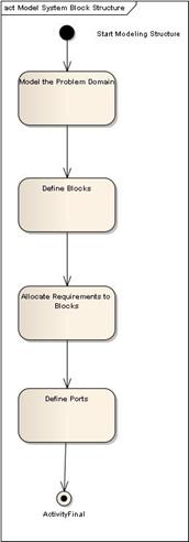
Blocks can be used to represent hardware, software, or just about anything else. Block definition diagrams represent system structure. Internal block diagrams describe the internals of a block such as parts, ports, and connectors.
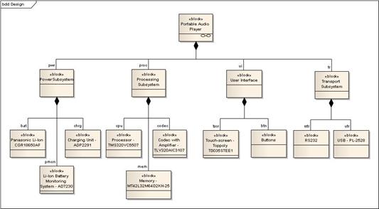
Figure 5 shows how our process roadmap approaches defining system structure.
If you think of a Block as an electronic circuit (one of many things that a Block can describe), the Ports define the input/output signals to and from the circuit. SysML allows you to describe the I/O signals and transformations in great detail, and EA contains a built-in simulator that allows you to plot the output graphically.
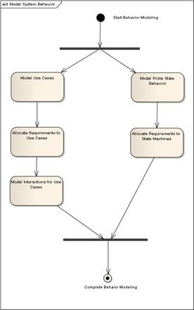
SysML provides four main constructs to represent different aspects of system behavior; use cases, activity diagrams, sequence diagrams, and state machines. As shown in Figure 6, our roadmap shows two parallel branches for modeling system behavior.
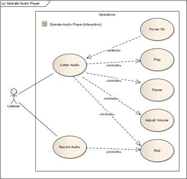
One branch starts with use cases [2], which describe scenarios of how users will interact with the system. Use cases generally consist of a "sunny-day" part, which describes a typical success-path for the scenario, and multiple "rainy-day" parts which describe unusual conditions, exceptions, failures, etc. Figure 7 shows a Use Case Diagram which organizes the scenarios in listening to the Audio Player.
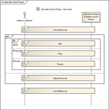
Use cases are typically detailed on Interaction (Sequence) Diagrams, which can also be drawn at a higher level. Figure 8 shows Interactions between the Listener and the Audio Player. Note the use of parallel paths on the Interaction Diagram.
The other branch on the roadmap involves defining event-driven, finite-state behavior of some part of a system using state machines. As a simple example, Figure 9 shows some finite state behavior associated with Playlist Maintenance for our Audio Player.
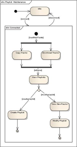
One of EA's unique capabilities is the ability to generate functional (algorithmic) code from state machines. As you'll see, these state machines can be realized in software or in hardware using Hardware Description Languages (HDLs).
Requirements are allocated to both use cases and states.
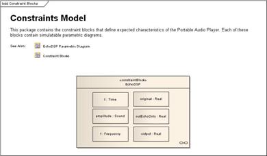
Parametrics allow us to define detailed characteristics, physical laws, and constraints on system blocks that allow us to simulate how a system will behave, then make engineering tradeoffs, and re-simulate until our design meets the specified requirements.
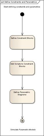
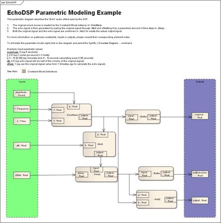
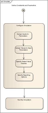
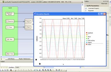
Our roadmap provides two high-level activities in this area; the first to define constraint blocks and parametric diagrams (shown in Figure 10 and illustrated in Figures 11 and 12), and the second to configure and execute the simulations (shown in Figure 13).
The ability to configure and execute simulations within EA, eliminating the need to export the model to external simulation software, is one of the unique capabilities of the Sparx SysML solution.
EA's built-in support for scripting and graphical display of simulation results tightens the feedback loop on making engineering tradeoffs in the model to rapidly ensure that all system requirements are met.
Hardware Description Languages allow the specification of electronic circuits in a software-like representation. According to Wikipedia[3]:
In electronics, a hardware description language or HDL is any language from a class of computer languages and/or programming languages for formal description of electronic circuits, and more specifically, digital logic. It can describe the circuit's operation, its design and organization, and tests to verify its operation by means of simulation.
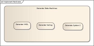
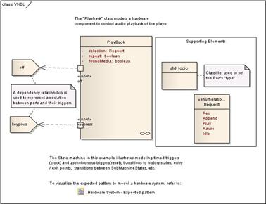
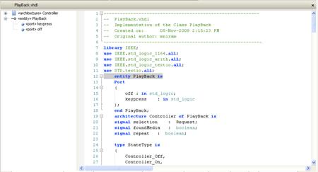
EA's long-proven ability to generate code has been extended to support code generation in VHDL, Verilog, and System C in the Systems Engineering Edition. While code generation is independent of SysML usage, from a process roadmap standpoint, this means we can drive both hardware and software implementation from our SysML model. Once code is generated in an HDL, it's possible to "compile to silicon" to realize the hardware solution on a chip. This process is shown in Figures 16 and 17, which show how a playback controller can be generated in VHDL.
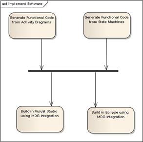
Software implementations can leverage a variety of powerful capabilities that are included with the System Engineering Edition of EA. Two of the more important and unique capabilities are:
Figure 18 shows a high-level look at the Software Implementation activity from the roadmap.
This article has presented a high-level overview of ICONIX Process for Embedded Systems, which leverages Enterprise Architect System Engineering Edition to build hardware/software models that are structured around the "four pillars of SysML". We've illustrated our process roadmap with diagrams from Sam Mancarella's Audio Player Example.
[1] OMG Systems Modeling Language Tutorial, INCOSE 2008
[2] See "Use Case Driven Object Modeling with UML: Theory and Practice" by Doug Rosenberg and Matt Stephens for a lot more information about use cases.
[3] Wikipedia Hardware Description Languages